

Industrial Electric Valve Actuation and Control Explained for Engineers
2026-11-02
Industrial electric valve actuation often gets treated as a footnote in control system design—until a process fails to respond the way the datasheet promised. This guide cuts through the usual boilerplate and walks through what engineers actually need to know: torque curves, duty cycles, feedback loops, and the control signals that keep valves doing what they're told. Whether you're retrofitting legacy infrastructure or specifying new builds, understanding how these actuators interact with your control architecture is what separates a reliable loop from a troubleshooting nightmare. At UPTAI, we see these challenges firsthand, and this series aims to give you practical, no-nonsense insight—starting with the fundamentals most vendor manuals skip.
Torque, Thrust, and Duty Cycle: Matching Actuators to Valve Requirements
Valve actuation begins with two distinct force demands. Torque is the rotational effort required to turn a quarter-turn valve stem against seating friction and media pressure, while thrust is the linear push or pull needed to stroke a rising-stem gate or globe valve. These values shift with service conditions—cold startup may increase packing friction, and solids in the flow can add breakaway resistance that steady-state calculations miss. A properly matched actuator delivers enough margin above the valve's maximum required torque or thrust without oversizing to the point where seating components suffer impact damage.
Duty cycle is often the quiet constraint. An actuator that handles a valve's peak torque once per shift may overheat or wear prematurely when asked to cycle every thirty seconds. Modulating service, where the stem holds intermediate positions against flow forces, demands continuous thermal capacity rather than a simple on/off rating. Manufacturers quote duty cycle as a percentage of operating time, but the practical question is whether the actuator's motor insulation, gear lubrication, and control electronics can tolerate the actual cadence of the process—including infrequent but hard emergency strokes.
Matching an actuator to a valve means reconciling these three variables rather than picking the largest available frame. Start with the valve's worst-case torque or thrust at minimum and maximum differential pressure, then apply a service factor that reflects how often that worst case occurs. Compare the required duty cycle against the actuator's thermal limit at the ambient temperature where it will live—not at a bench-test condition. Finally, account for control type: a spring-return pneumatic actuator sized for torque-based seating may deliver less thrust at the end of its stroke if the spring nears its compressed length. The goal is not a universal fit but a pairing that stays predictable across the valve's actual operating envelope.
Control Signal Architectures: From Hardwired Relays to Fieldbus and IIoT
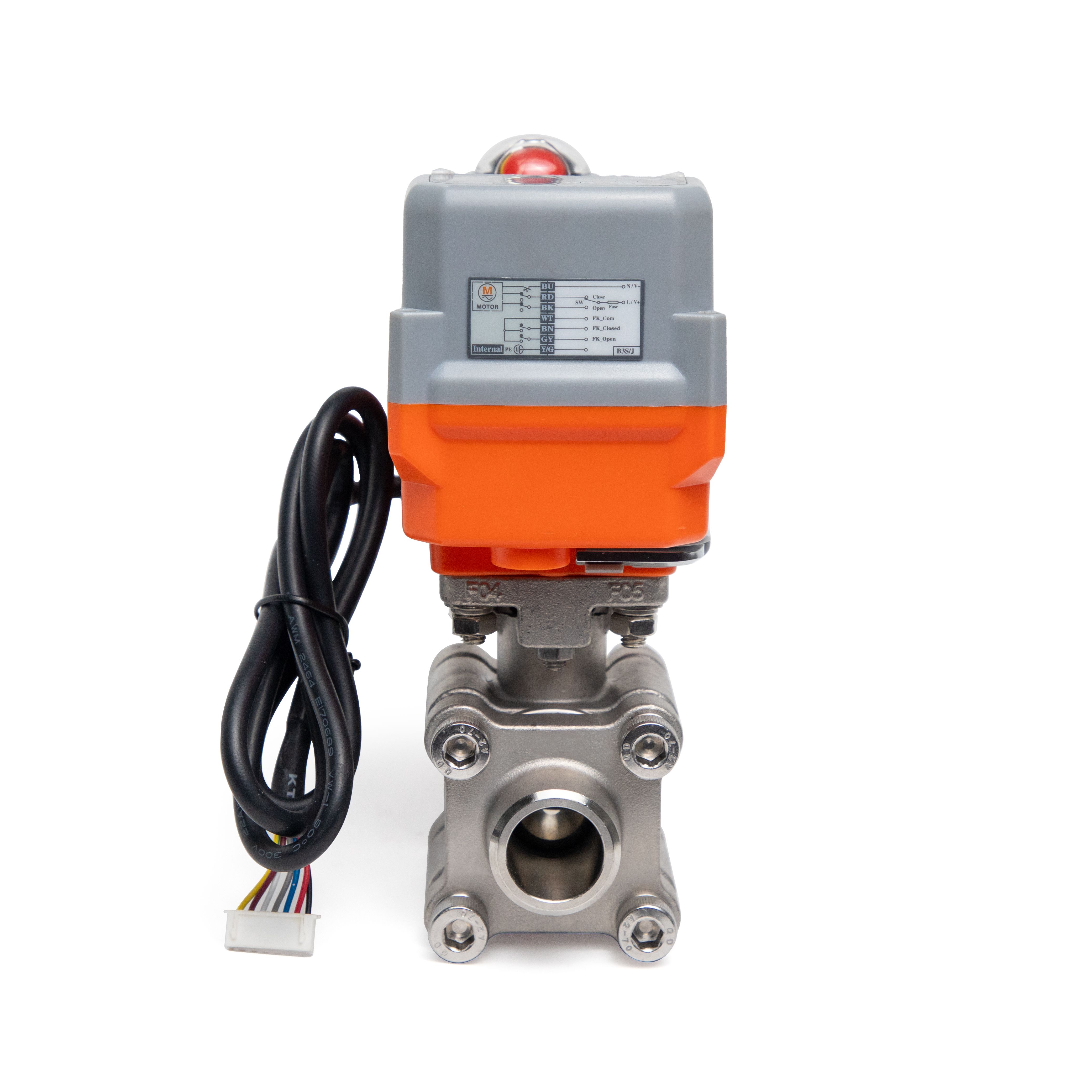
Early control systems relied on hardwired relays, where each signal traveled through a dedicated physical conductor. A start button, a limit switch, or an emergency stop each had its own wire running back to a relay panel. Modifying logic meant moving jumpers and rewiring terminals, and troubleshooting involved tracing cables through bundles. These systems were bulky, inflexible, and prone to wear at every mechanical contact.
The shift to fieldbus protocols in the 1980s and 1990s replaced that dedicated wiring with a single digital network. Devices like sensors, actuators, and drives could share a twisted-pair or fiber-optic cable, exchanging not just on/off states but diagnostic data, calibration values, and configuration parameters. This cut installation costs dramatically, especially for plants with thousands of I/O points spread across large areas.
Today, IIoT extends control architectures beyond the plant floor. Ethernet-based protocols such as PROFINET, EtherNet/IP, and EtherCAT merge real-time control with IT systems, while wireless sensors and edge gateways feed data to cloud platforms. The architecture is no longer a fixed hierarchy of PLCs and remote I/O—it becomes a mesh of smart nodes that can be reconfigured, monitored, and optimized from anywhere, blurring the line between operational technology and enterprise networks.
Motor Technologies Compared: Squirrel Cage, PMSM, and Stepper in Valve Service
Valve actuators rarely reward a one-size-fits-all motor choice. A squirrel cage induction motor brings simple, rugged construction and handles continuous duty without complaint, but it struggles to hit exact partial-stroke positions unless paired with an encoder and a variable frequency drive. Permanent magnet synchronous motors step into that gap with higher torque density and tighter speed regulation, making them a natural fit for modulating valves that cycle frequently. Stepper motors occupy the opposite end: they shine in small, low-inertia valve assemblies where discrete positioning matters more than raw torque, though they can lose steps if the load spikes unexpectedly.
Control effort separates these three more than nameplate data suggests. Squirrel cage machines need external speed feedback and a VFD to move beyond coarse open-loop operation. A PMSM demands a more sophisticated drive running field-oriented control, but it rewards that complexity with smooth low-speed torque and better energy efficiency during partial load. Steppers skip most of that hardware—just pulse and direction—but the trade-off is a narrow sweet spot. Once resonance or backdriving torque enters the picture, missed steps become a real risk in valve applications with varying friction.
Maintenance and lifetime costs also diverge. Squirrel cage motors have no magnets or brushes, so they tolerate heat and dirty environments with little attention. PMSMs use rare-earth magnets that can demagnetize under extreme temperature or fault conditions, and their drives need careful thermal management. Steppers are cheap to replace and simple to wire, but their bearings and rotor inertia wear faster in high-cycle valve duty. Choosing among them usually comes down to how precisely the valve must move, how often it must move, and what happens if it stops in the wrong spot.
Position Sensing and Feedback: Encoders, Potentiometers, and Limit Switches
Any motion system that cares about where it is—or where it should stop—relies on some form of position sensing. The three workhorses here are encoders, potentiometers, and limit switches, each with its own character. Rotary encoders, whether incremental or absolute, give you fine resolution and fast updates, which makes them the go-to for servo loops and CNC axes. Potentiometers are simpler and cheaper: a resistive track and a wiper produce a voltage proportional to position, ideal for low-speed adjustments or panel controls. Limit switches, by contrast, don't tell you the position within the range; they just signal when a mechanical end has been reached, which is often all you need for homing or preventing a crash.
Choosing among them is less about picking a 'best' device and more about matching failure modes to your application. An incremental encoder can lose counts after a power glitch, so many designs pair it with a limit switch for reference. Potentiometers wear out quickly if they're constantly moving, and their analog signal can drift with temperature; still, for a throttle pedal or a joystick they're hard to beat on cost. Limit switches can be mechanical, magnetic, or inductive—mechanical ones are cheap but have a finite life, while non-contact versions survive harsh environments but cost more. If you need absolute position right after startup, an absolute encoder or a multi-turn pot might save you from a homing routine, but that adds complexity to the interface.
Failure Modes and Safety Integrity: Designing for Spring Return and ESD
Actuators with spring return mechanisms often face a classic trade-off between fail-safe behavior and long-term reliability. The spring itself, while essential for driving the valve to a safe position on loss of power or signal, can introduce failure modes such as fatigue, relaxation, or breakage after repeated cycles. A poorly sized spring may not deliver enough torque at the end of its stroke, leaving the valve partially open when it should be fully closed. This partial stroke condition is dangerous in emergency shutdown systems because it undermines the assumed safety integrity. Engineers need to verify the spring's end-of-life torque, not just its initial force, and account for friction buildup in the actuator stem or gearbox that can further reduce available margin.
In ESD applications, the interaction between the spring return action and the overall safety instrumented function requires careful attention to diagnostic coverage and proof testing. Many failure modes are not self-revealing; a spring can crack internally yet still hold the valve open under normal operating pressure. Only a full or partial stroke test can expose such latent faults. The challenge is to design the actuator so that a partial stroke test does not wear out the spring prematurely or mask degradation. Using smart positioners that record torque profiles and compare them against baseline signatures helps detect gradual spring weakening before it leads to a dangerous failure. This approach shifts the maintenance strategy from fixed intervals to condition-based, improving safety integrity without unnecessary downtime.
Another overlooked aspect is the common cause failure between the spring return and the ESD logic solver. If a power failure simultaneously de-energizes the solenoid valve and the spring is relied upon to close the valve, both elements share the same trigger. For high SIL requirements, designers often add redundancy through a second independent shutdown path or use a mechanical latch that holds the valve open until a dedicated trip signal releases it. The key is to avoid assuming that a spring return alone guarantees safe failure. Instead, treat the spring as one component within a larger safety loop, subject to the same rigorous failure rate data, environmental stress screening, and proof test intervals as any electronic or pneumatic element in the chain.
Commissioning and Diagnostics: Tuning, Partial Stroke Testing, and Predictive Maintenance
Commissioning starts with tuning the positioner or control loop to match the valve assembly's actual response. Instead of relying on default settings, field technicians often nudge gain and damping values while watching the stem move with a handheld communicator. Small adjustments at low signal levels can prevent overshoot that only shows up later under process pressure. This hands-on tuning step is what separates a stable startup from one that hunts for days.
Partial stroke testing gets treated as a compliance checkbox, but it's more useful as a diagnostic routine. A well-designed test ramps the valve a few percent off the seat and captures breakaway torque, travel time, and pressure differential. Comparing those values against the baseline from commissioning reveals sticking, seat wear, or air supply problems long before a full stroke fails. Skipping the baseline or ignoring trends turns the test into noise.
Predictive maintenance works when diagnostics feed into a work order system without human translation. Instead of scheduling rebuilds on a calendar, plants watch for small drifts in friction, leak rate, or response time. An alert only matters if it includes the likely cause and recommended action—otherwise maintenance teams learn to ignore it. That loop from tuning baseline to partial stroke data to work order is what makes predictive maintenance practical rather than a buzzword.
FAQ
Electric actuators eliminate the need for a compressed air supply and can hold a valve position without continuous energy input, which reduces operating cost. Their stepper or servo motors allow finer positioning resolution, and they integrate natively with digital control networks for closed-loop modulation.
Start with the valve manufacturer's published break and run torque values under actual process conditions. Add a safety factor typically between 1.25 and 1.5 to account for seat wear, debris, or thermal expansion. Never size based solely on line pressure because seat friction can dominate torque demand.
Most units provide a 4-20mA position transmitter as standard, but advanced models include HART, Modbus RTU/TCP, or Profibus. Some also output open/close limit switches and mid-travel alarm relays. Selecting a digital protocol allows remote configuration and retrieval of diagnostic data.
Yes, many are certified for hazardous areas. Look for ATEX or IECEx markings with appropriate protection concepts such as Ex d (flameproof), Ex e (increased safety), or Ex tb (dust). The specific zone and gas group must match the actuator's certificate, and the temperature class must stay below the ignition temperature of the process fluid.
Open/close actuators are designed for infrequent operation, often only a few times per day, and use lower-cost induction motors. Modulating actuators handle continuous position changes, so they incorporate high-resolution feedback, thermal protection, and motors rated for frequent starts. Using an open/close unit on modulating service leads to overheating and premature failure.
They log torque profiles, motor temperature, number of starts, and travel time trends. Deviations from the baseline torque curve can indicate valve seat wear, stem binding, or gear train degradation. Maintenance teams can pull this data remotely and schedule repairs before a complete failure interrupts production.
Confirm the actuator's supply voltage, phase, and frequency match site power. Size conductors to limit voltage drop during motor inrush, especially for long cable runs. Use shielded, twisted-pair cables for control signals, separate them from power conductors, and install surge protection if the site experiences frequent lightning or switching transients.
Duty cycle defines how often the motor can run without exceeding its thermal limit. For example, an S4 30% duty means the motor can operate 30% of a cycle period. Exceeding that rating causes insulation breakdown and motor burnout. Engineers should also consider ambient temperature, as hot environments derate the allowable duty cycle.
Conclusion
Engineers sizing electric actuators quickly learn that catalog torque values mean little without matching the valve's thrust profile, seating requirements, and duty cycle. A quarter-turn ball valve may demand high breakaway torque but modest running torque, whereas a globe valve with tight shutoff needs sustained thrust at the seat. Oversizing wastes energy and stresses the valve stem; undersizing leads to stalled motors and thermal trips. Control architecture decisions follow from this mechanical foundation. Hardwired relay panels still suit small standalone systems, but modern plants increasingly adopt fieldbus and IIoT links that expose actuator health, command status, and diagnostic counters to central controllers. Motor selection adds another layer: squirrel cage induction motors remain rugged and cost-effective for continuous duty, PMSM offers higher efficiency and torque density for frequent modulating service, and stepper motors suit low-speed precise positioning where holding torque matters more than speed.
Position feedback choices shape how reliably the valve reports its state. Potentiometers work for basic open/close indication but wear in modulating duty; encoders deliver resolution needed for tight loop control; limit switches provide simple end-of-travel confirmation that can back up analog feedback. Failure modes then drive safety design. Spring-return actuators guarantee a fail-safe position on loss of power or signal, and ESD circuits must be tested against real valve loads, not just bench conditions. Commissioning is where many problems surface: torque limiting must be tuned so the actuator seats the valve without hammering it, partial stroke testing verifies emergency shutdown capability without disrupting process flow, and predictive maintenance uses motor current signature or vibration trends to catch stem wear, gear backlash, or lubrication breakdown before they cause unplanned downtime.
Contact Us
Contact Person: Adonis
Email: [email protected]
Tel/WhatsApp: 8615858822657
Website: https://www.uptaivalve.com