

Current Sense Resistor Top Picks for Precision Analog and Power Designs
2026-10-19
Precision analog and power designs often live or die by one small component: the current sense resistor. Picking the wrong one can quietly degrade accuracy or efficiency. In this post, we highlight a handful of favorites that consistently deliver in real-world circuits. Whether you're fine-tuning a battery monitor or pushing a motor driver, these parts deserve a close look. Need deeper technical guidance? Milliohm has you covered.
How Tolerance and Temperature Drift Decide Measurement Accuracy
In precision measurement circuits, the resistor network and voltage reference rarely sit exactly at their nominal values. Manufacturing tolerance sets the initial spread—say a 0.1% resistor might be off by 1000 ppm right out of the box. That fixed offset can often be calibrated away at room temperature, but it still defines the baseline uncertainty before any correction is applied.
Temperature drift introduces a different kind of error because it moves with the environment. A resistor with a 25 ppm/°C temperature coefficient will shift 250 ppm across a 10°C span, and this change cannot be removed by a single calibration point. The same applies to reference voltages, amplifier offset drift, and even the thermocouple effects at solder joints. When you combine these contributions, a measurement that looked stable on the bench can lose several counts of accuracy in a modest thermal swing.
A practical way to think about total error is to add the worst-case tolerance to the worst-case drift over the expected operating range, though many designs use a root-sum-square estimate for more realistic numbers. If you need 0.01% accuracy over 0–50°C, for example, selecting parts only by their room-temperature tolerance will almost certainly fail. The temperature coefficient usually matters more than the initial tolerance once the system leaves the calibration environment.
Four-Terminal Sensing and Layout Choices That Minimize Parasitic Error
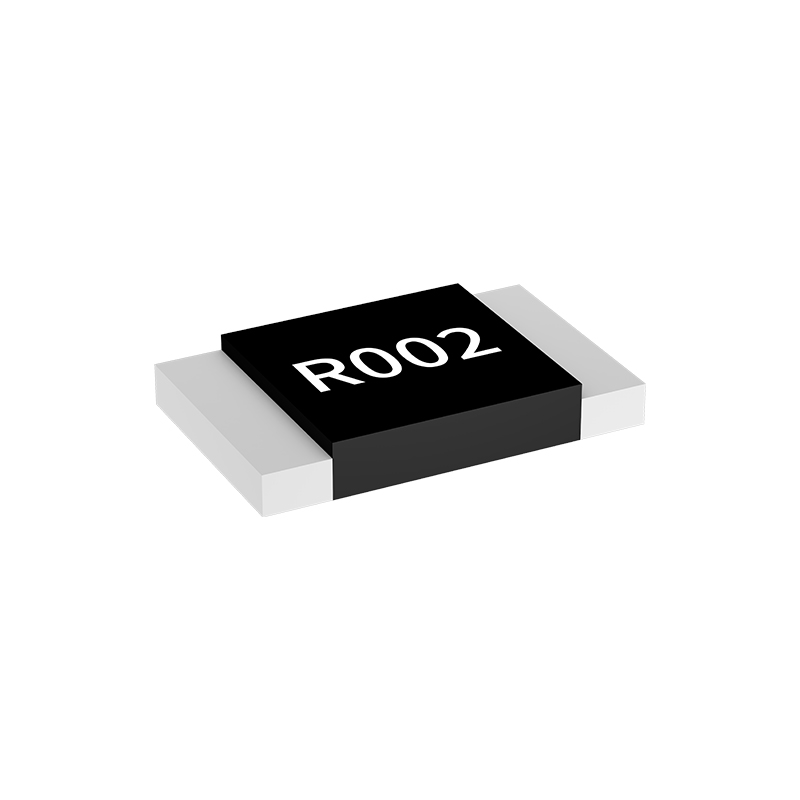
Four-terminal sensing cancels the voltage drop in current-carrying traces by separating the force and sense connections at the resistor terminals. The force pair carries the load current, while the sense pair draws almost no current, so the copper resistance between the tap point and the measurement circuit has negligible effect. In layout, the sense traces must land directly on the component pads, not on a nearby section of the high-current trace. Any distance between the sense tap and the resistor body adds a parasitic resistance that scales directly with load current, producing a measurement offset that no amount of calibration can fully remove if it changes with temperature or current level.
The physical arrangement of vias and copper around a four-terminal sense resistor matters as much as the schematic. Connect each sense line to its own dedicated via placed at the resistor pad edge, and never share a via between a force trace and a sense trace. A shared via forces a small portion of the load current through the sense path, reintroducing milliohm-level copper resistance that can swamp a 10 mΩ sense resistor. Differential routing of the sense pair also helps reject magnetic pickup from nearby switching nodes, but the traces must stay close together and follow the same path to keep loop area small.
Thermal gradients across the sense component generate thermocouple voltages at every junction between dissimilar metals, including the solder joint and the via plating. Place the sense resistor away from hot power stages, and orient it so heat spreads evenly across the two sense terminals. Keep high-current copper pours from passing under or near the sense traces, because the voltage gradient in a power pour can couple into the sense lines through common impedance or stray capacitance. Symmetry in pad shapes, via counts, and thermal relief patterns is often what separates a current measurement that holds 0.1% accuracy from one that drifts several percent over load and temperature.
Metal Foil, Thin Film, and Metal Strip Compared for Noise and Stability
In precision resistor networks, noise and long-term drift often matter more than initial tolerance. Metal foil elements made from rolled nickel-chromium foil bonded to a ceramic substrate tend to generate extremely low excess noise because their conduction path is a continuous, homogeneous metal layer with few grain boundary interruptions. Thin film parts, usually sputtered or evaporated onto a substrate, can be quieter than thick film but still contain microscopic discontinuities and higher sheet resistance non-uniformities that contribute slightly more flicker noise under DC load. Metal strip, sometimes called bulk metal or shunts, uses a thicker, stamped or etched alloy piece that provides a very low resistance and low thermal EMF, but its larger mass and different current distribution can introduce higher parasitic inductance, which may affect stability in fast-switching circuits.
When comparing these three for long-term stability, metal foil shows a clear advantage in reversible drift under temperature cycling because the foil is work-hardened and then thermally stabilized, yielding predictable, low TCR and excellent load-life behavior. Thin film resistors can drift more noticeably after soldering and thermal shock due to micro-cracking or stress relaxation in the nanometer-scale layer. Metal strip devices excel in high-current pulse handling and low ohmic values; their stability is generally good under steady-state power but can degrade if the termination welds or the alloy’s self-heating cause localized thermomechanical strain. For circuits that must hold a ratio over years, foil often wins, while strip is chosen for current sensing where noise is not the limiting factor.
A practical distinction is that low noise does not always equal most stable, and the choice depends on the operating point. At high resistance values, metal foil’s homogeneous structure keeps flicker noise down to nearly thermal limits, while thin film may show a few decibels more at low frequencies. But if the application uses very low resistance with large current swings, metal strip’s low ohmic value means less voltage noise from the resistor itself, and its high mass spreads heat quickly, preventing localized hot spots that would otherwise create drift. Each material has a crossover where its noise spectral density and stability under load diverge, so direct comparison should be done under the exact bias and environment rather than relying on datasheet adjectives.
Thermal Derating and Power Handling Without Compromising Board Space
Board designers often treat thermal derating as a penalty, but it is really a design lever. A resistor rated for 1 W at 70°C might need to drop to 0.5 W at 125°C, and that curve forces you to either pick a bigger part or accept a shorter life. The trick is to spread heat through the PCB instead of chasing larger component footprints. Copper pours, thermal vias, and careful placement near board edges can lower the actual hot-spot temperature enough to keep the same 0402 or 0603 package within its derated envelope.
Power handling gets interesting when you stop thinking in package size alone. A 0805 chip resistor might handle 0.25 W on a standard two-layer board, but with a solid ground plane underneath and wider pad connections, the same part can often sustain 0.5 W without violating its maximum film temperature. This lets you keep the board area small while still meeting surge or steady-state dissipation requirements. The key is verifying the thermal path, not just the datasheet number.
For compact designs, material choice matters as much as layout. Thicker copper, higher thermal conductivity laminates, and even selective use of aluminum-core PCBs can pull heat away from small components without increasing their spacing. The result is a dense layout that meets derating guidelines at elevated ambient temperatures, with no extra board real estate spent on oversized parts or heat sinks.
Pulse Withstand and Overload Margins in High-Side Current Paths
Pulse withstand in a high-side current path depends on more than the datasheet current rating. Junction temperature swing, bond wire heating, and how quickly heat spreads into the leadframe all shape whether a short overload causes permanent damage. A 2 ms pulse can create localized hot spots far beyond steady-state limits even when average power looks small.
Overload margin should be separated into two failure modes: immediate thermal runaway during the pulse, and cumulative fatigue from repeated inrush cycles. The actual margin varies with duty cycle, switching frequency, and current waveform shape. A capacitive load can draw five times the continuous rating for a few milliseconds, yet remain safe if the pulse energy stays within the transient thermal impedance curve.
Checking the measured current profile against the transient thermal impedance is more useful than comparing peak current to a single number. Parasitic trace resistance and bulk capacitance limit how quickly energy reaches the switch, so simulations need those elements. A 20% peak current margin can mislead if the pulse duration falls in a region where thermal impedance rises sharply. Instead, verify that the time-temperature trajectory stays below maximum junction temperature with enough derating for process variation and aging.
Value Selection and Long-Term Drift in Precision Analog Front Ends
Precision analog front ends live or die by the passive components tucked around their amplifiers and converters. Choosing resistor values is not just about hitting a gain target; it is about understanding the trade-off between noise, power, and input bias current effects. A high-value feedback network keeps quiescent current low but turns bias currents into noticeable offset voltages and invites thermal noise. Dropping the impedance, on the other hand, can load the driving stage and force it into distortion. The practical sweet spot is usually found by mapping the front end's total error budget against the real source impedance and the amplifier's current noise density, not by copying a reference design wholesale.
Long-term drift is the quiet assassin of precision. Even film resistors with tight initial tolerance can wander by hundreds of parts per million over a decade as moisture, thermal cycling, and mechanical stress slowly rearrange their internal structure. Thin-film parts on ceramic tend to be far more stable than thick-film on epoxy, but the layout matters just as much: matched resistor pairs should be placed close together, oriented the same way, and kept away from board edges or mounting holes where stress concentrates. A poorly chosen decoupling cap or a board material with high moisture absorption can add more drift than all the active circuitry combined.
The real skill is not picking a single perfect value but designing for predictable degradation. By treating drift as a statistical variable with a known distribution, you can set acceptance limits that keep the front end within specification for the product's intended life. Burn-in and accelerated aging tests on the first production run often reveal which passive components are the weak links, allowing you to swap a marginal part before it becomes a field failure. In precision work, the difference between a good design and a great one is rarely the op amp; it is how carefully the resistors, capacitors, and board materials are selected and stress-tested.
FAQ
Precision analog circuits demand tight initial tolerance, low temperature coefficient of resistance (TCR), and stable long-term drift. A suitable sense resistor typically offers 0.1% or better tolerance, TCR below 50 ppm/°C, and uses bulk metal foil or thin film elements to minimize self-heating and thermal EMF.
It separates the current-carrying electrodes from the voltage-sensing electrodes, effectively eliminating lead resistance and contact resistance errors. This becomes critical when the sense resistor value is below 10 milliohms, where even small parasitic resistances can dominate the measurement.
In battery monitoring, the sense resistor must maintain its value across a wide temperature range. A low TCR (e.g., ±25 ppm/°C) ensures that the current reading remains accurate as the pack heats or cools, preventing state-of-charge estimation errors.
Manganese-copper alloy (Manganin) resistors are a strong pick for high-current paths due to their very low TCR and excellent thermal stability. For surface-mount needs, metal alloy chips with welded copper terminals offer low resistance values and high power handling.
In pulse applications, the resistor does not reach thermal equilibrium. The limiting factor becomes the instantaneous energy or surge capability rather than continuous power dissipation. A resistor with high pulse endurance (e.g., thick film or wirewound) can handle short bursts well beyond its steady-state rating.
A larger sense resistor increases the voltage drop for a given current, which boosts the signal above the noise floor. However, it also introduces more power loss and voltage burden. Designers typically target 50–100 mV full-scale drop to balance resolution against efficiency.
Inductance in the sense resistor creates voltage spikes proportional to di/dt, corrupting the instantaneous current signal. Choosing a low-inductance construction (such as a four-terminal chip with Kelvin geometry or a coaxial shunt) minimizes these transients and preserves measurement bandwidth.
Yes. Thermal relief and copper area directly affect heat dissipation and solder joint reliability. For low-ohmic resistors, PCB trace resistance can add to the sensed path unless Kelvin sensing is used. Placing the resistor away from heat sources and using dedicated sense traces prevents measurement drift.
Conclusion
Selecting a current sense resistor for precision analog and power designs rarely comes down to a single data-sheet number. Tolerance and temperature coefficient set the baseline measurement error, but the real accuracy story emerges once you account for how the part behaves under load and across temperature swings. A resistor that looks stable at 25°C can drift enough at 85°C to swamp a 16-bit ADC, so matching the tempco to your front-end's least significant bit budget matters more than chasing an idealized 0.1% spec.
Layout and construction choices often outweigh the resistor's printed value when parasitic errors creep in. Four-terminal Kelvin connections keep trace resistance and solder joint effects out of the sensed voltage, which is critical below roughly 10 mΩ. Among available technologies, metal foil and thin film tend to deliver lower noise and better long-term stability than metal strip, though strip parts usually win on pulse and overload margins—especially in high-side power paths where short-circuit currents appear without warning. Thermal derating also needs a hard look: a part rated for 1 W may need to sit at half that once you factor in dense board heating. In precision analog front ends, value selection should anticipate long-term drift from moisture, thermal cycling, and mechanical stress rather than simply meeting today's tolerance. Picking the right resistor therefore means balancing immediate accuracy against how the part will age inside the final product.
Contact Us
Contact Person: Yuying Gao
Email: [email protected]
Tel/WhatsApp: +86 18926013721
Website: https://en.milliohm.net/